Rapid Prototyping & Rapid Manufacturing Expert
Specialize in CNC machining, 3D printing, urethane casting, rapid tooling, injection molding, metal casting, sheet metal and extrusion
Design for CNC Prototyping
DDPROTOTYPE has many years of CNC machining experience, has accumulated a large number of designs for CNC prototyping, and are very willing to share with customers, hoping to bring you design help.CNC machine tool is an excellent technology, which can provide various possibilities for precise CNC prototyping and make your final product as good as your original design. When CNC machining any prototype, some main considerations must be taken into account, including its complete geometry.
So far, such a guide is more a rule of thumb than an actual agreement. Industry standards are rare, and technology is constantly changing, and exciting new innovations have been proposed, which have reached the limit of possible and impossible things. However, there are many practices that have become real rules to try and follow. These are some limitations and considerations attached to the design of CNC machining parts.

Basic Rules
In general, it is best to design prototypes with larger diameter tools to machine them. This helps avoid the use of special tools and ensures faster CNC machining. It is better not to design a cavity four times its width. It is essential to ensure that the design functions are consistent with the main directions allowed by the machine. This involves the number of axis of CNC machines needed for machining.
When you try to machine text or letters, it is best to use engraved text instead of embossed text. The relief text will eventually use a large number of materials that need to be removed in the whole CNC machining. Of course, a minimum of 20 point sans serif font is recommended to avoid unnecessary trouble in engraving text.
It is better to submit technical drawings when working with our machinist, and it is better to mark the tolerance in key parts. These parts must have a very specific format, but can greatly help you complete the design of the prototypes and display the best quality.


Machine types
Before considering prototype machining, we should pay attention to the limitations and advantages of CNC machine tools. All kinds of CNC machine tools can control some prototype machining shapes and tolerances. Some of the most common types and their benefits are listed below.
CNC lathe is usually used for the prototype machining of complicated cylinder shape. Because of its powerful function, the lathe usually has accurate tolerance and cost-effective operation, so it is most commonly used in the processing of these circular prototypes. When a lathe is used, the material rotates while it remains stationary in the turning tool, so the geometry of the prototype depends on the motion and feed speed of the stationary tool as well as the speed control. The lathe is designed for turning, so it has no greatest advantage. The accuracy of the lathe will decrease with the thickness of the materials used.
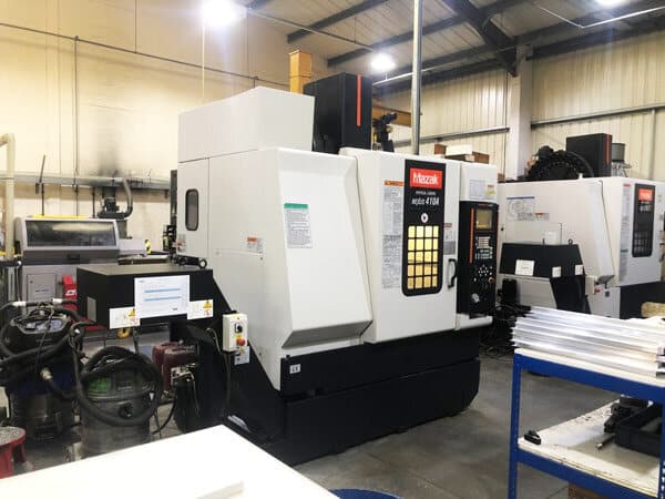
There are many kinds of CNC milling machines. The main difference between them and lathe is that the movement of cutting tool is opposite to that of material. The vertical milling machine has a spindle axis and a cutting tool aligned perpendicular to the machine bed. The cutter of the horizontal milling machine is installed on the horizontal spindle of the workbench. Generally, they can be used when a cutter is required to remove a large amount of material or when the accuracy requirements are low. Machines with more shafts can take advantage of and combine the advantages of lathes and milling machines in one setup.

Tool restriction
One of the most common rules of thumb in machining is the ratio of tool diameter to cavity depth. The recommended depth of any cavity in the design is within four times its width, because the cutting length of the end mill is limited. This is usually three to four times the diameter of the tool. A lower aspect ratio will result in increased vibration, tool deflection and chip evacuation.
Another common limitation that must be remembered is the geometry of the milling tool. A large number of CNC milling tools are cylindrical, and the milling length may be limited. This shape has an effect on the final milling. For example, the inside corner of a block always has a radius. This is true even when they are machined with very small cutting tools.

Special tools can help solve some of these problems, but they can avoid them as much as possible, depending on the economic benefits and time. If the length of the tool gives you the problem of not being able to reach the depth of the cavity in the workpiece, you can use a special tool with a longer axis, but bear in mind the disadvantages. Longer tools increase vibration and reduce the accuracy you can achieve. The design of parts should usually be aimed at using tools with larger diameter and shorter length, which is the most feasible for users.
Inner edge
When designing the inner edge of a prototype, the most commonly recommended vertical corner radius is one-third or more of the cavity depth. When using the recommended corner radius, use a diameter tool that follows the recommended cavity depth guidelines. In order to obtain a higher quality surface finish, it is better to make the corner radius slightly higher than the recommended amount. This allows the tool to cut along a circular path rather than a 90 degree angle. However, if you want to use a 90 degree angle, it is recommended to use a T-bone undercut as described below, rather than selecting a reduced corner radius.

Thin-Wall
Thin walls can be tricky because reducing the wall thickness reduces the stiffness of the material, increasing vibration during machining and reducing the accuracy that can be achieved. In addition, for plastics and other materials susceptible to temperature, it is best to monitor softening and residual stresses. Larger minimum wall thickness can reduce these factors. The recommended minimum values vary depending on the material and tool, but the general mechanic guidelines are: 0.8mm for metal and 1.5mm for plastic.

Hole
When there are holes, it is best to keep the drilling depth low unless it is absolutely necessary, and do not enter the flat bottom holes, because these holes may be very difficult or require special tools. When machining holes with drill or end mill, reamers and boring tools are needed to finish the holes with small tolerance. For high precision holes smaller than 20 mm, standard diameters are strongly recommended. Non standard diameter holes shall be machined with end mills. In this case, the maximum cavity depth limit applies. Use a special drill (minimum diameter 3 mm) to machine any hole deeper than the typical recommended value of the tool.

For extended holes, parts can be drilled from both sides, but it is important to recognize that the location where the two holes meet will not match. In order to solve this mismatch problem, users can apply jig.
For edge drilling, it is important to ensure that the entire diameter of the bit is contained in the part. If this is not the case, the bit may break, the surface finish may deteriorate, and the sharp edges formed at the corners may fold. If absolutely necessary, drill the part first, then mill off the material to leave a local hole.
Chamfer and Fillet
A chamfering is a beveling cut in which two surfaces meet at sharp edges. This helps simplify the assembly of the bolt into the hole and reduces the risk of injury when handling sharp objects. Deburring can achieve similar purpose, but the edge of the part should be damaged. In many cases, this reduces the size, so chamfering the material is better for a specific size. In addition, the edges of chamfers shall be maintained at 45 ° unless the use of another angle is essential.

Fillets need to fillet the inside or outside corners of the part. It is better to make any radius on the part larger than the tool radius, so as to make the machining process easier. On the other hand, the internal fillets should be as large as possible to allow the use of large diameter tools, thus reducing processing time. Generally, the radius of the internal fillet should be greater than 1 / 3 of the cavity depth to avoid tool damage.


