

Rapid Prototyping & Rapid Manufacturing Expert
Specialize in CNC machining, 3D printing, urethane casting, rapid tooling, injection molding, metal casting, sheet metal and extrusion
Follow me on: 


Guide For Plastic Injection Molding
DDPROTOTYPE is a leading plastic injection molding manufacturer in China. It takes about 20 minutes to read the guide for plastic injection molding based on 15 years of experience.
The First Part--What is Injection Molding
What is plastic injection molding?Plastic Injection molding is a manufacturing technology for mass production of the same plastic parts with high tolerance. In plastic injection molding, polymer particles are first melted, then injected into the mold under pressure, in which the liquid plastic cools and solidifies. The materials used in injection molding are thermoplastic polymers that can be colored or filled with other additives.
Almost all the plastic parts around you are made by plastic injection molding: from automobile parts to electronic shell, to daily necessities. Plastic Injection molding is so popular because the cost of a single plastic product is very low in mass production.Plastic Injection molding has high repeatability and good design flexibility. The main limitations of injection molding are usually attributed to economic factors, as a higher initial investment is required. Moreover, the turnaround time from design to production is very slow (at least 3 weeks).

Injection Molding Technology
Today, injection molding has been widely used in consumer products and engineering applications. Almost all the plastic items around you are made by injection molding. This is because the technology can produce the same parts at a very low cost for a single part and a very large quantity (typically 1000 to 100000 + units).
However, compared with other technologies, the start-up cost of injection molding is relatively high, mainly due to the need to customize the mold. Molds cost between $1000 and $200000, depending on their complexity, materials (aluminum molds or steel molds) and accuracy (prototypes, medium or mass production molds).
Plastic Injection Molding Matrerial
All thermoplastic materials can be injection molded. Some types of silicone and other thermosetting resins are also compatible with the injection molding process. Most commonly used materials for injection molding:
Polypropylene (PP): about 38% of global production
Abs: about 27% of global production
PE: about 15% of global production
Polystyrene (PS): about 8% of global production
Even if we consider all other possible manufacturing technologies, injection molding of these four materials alone accounts for more than 40% of all plastic parts produced in the world every year!

Injection molding machines: how do they work?
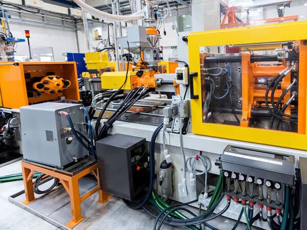
The injection molding machine consists of three main parts: injection molding unit, mold (the core of the whole process) and clamping / ejection unit. In this section, we will examine the purpose of each system and how their basic operating mechanisms affect the final results of the injection process. In the video below, a large injection molding machine can produce about 30 plastic parts every 3 seconds.

Plastic Injection Molding Video | DDPROTOTYPE
The Process of Plastic Injection Molding
The purpose of the injection unit is to melt the raw plastic and guide it into the mold. It consists of hopper, barrel and reciprocating screw.This is how the injection process works:
1. First dry the polymer particles and put them into the hopper, where they are mixed with coloring pigments or other reinforcing additives.
2. Feed the particles into the barrel, heat them at the same time, mix them and move them to the mold through the variable pitch screw. The geometry of the screw and barrel is optimized to help build the pressure to the right level and melt the material.
3. The ram then moves forward and the molten plastic is injected into the mold through the runner system, which fills the entire cavity. As the material cools, it re solidifies and forms the shape of the mold.
4. Finally, the mold opens and the solid parts are now pushed out by the thimble. Then close the mold and repeat the process.
The whole process can be repeated very quickly: it takes about 10 to 180 seconds, depending on the size of the part. When the part is ejected, it is assigned to a conveyor or holding container. In general, injection molded parts can be used immediately, with little or no post-processing.
Mold manufacturing
A mold is like a photographic negative: its geometry and surface texture are transferred directly to the injection molded part. Molds usually account for the largest part of the start-up cost of injection molding: for simple geometry and relatively small production (1000 to 10000 units), the cost of a typical mold is about $2000-5000, up to $100000. Suitable for die optimized for full production (100000 or more). This is due to the high level of expertise required to design and manufacture high-quality molds that accurately produce thousands (or hundreds of thousands) of parts.

The mould is usually made of aluminum or steel by CNC machining and then finished to the required standard. In addition to the negatives of parts, they also have other functions, such as the runner system that allows materials to flow into the mold, and the internal water cooling channel that helps and accelerates part cooling.
Typical case — Lego building blocks
Lego blocks are one of the most famous examples of injection molded parts. They were made using molds, like the ones in the picture, which produced 120 million Lego blocks (15 million cycles) before they were discontinued. Lego building blocks are made of ABS because of its high impact resistance and excellent plasticity. Each brick is perfectly designed with a tolerance as low as 10 microns (or one tenth of a hair). This is achieved by using best design practices, which we will study in the next section (uniform wall thickness, draft angle, ribs, embossed text, etc.).

The second part–Injection molding design
There are several factors that may affect the quality of the final product and the repeatability of the process. In order to generate the full benefits of this process, designers must follow certain design guidelines. In this section, we outline common defects in injection molding and the basic and advanced guidelines to be followed when designing parts, including recommendations to minimize costs.
Common injection molding defects
Most of the defects in injection molding are related to the uneven flow or cooling rate of the molten material during the melting process.
Here we list the most common defects in the design of injection molding parts. In the next section, we will show you how to avoid these defects by following good design practices.
warping
When some parts cool (and therefore contract) faster than others, they may bend permanently due to internal stresses. Plastic parts with uneven wall thickness are most likely to warp.

Shrinkage mark
When the interior of a part solidifies before its surface, a small dent may appear on the originally flat surface, which is called a dent. Parts with poor wall thickness or rib design are most likely to shrink.

Drag marks
As the plastic shrinks, it puts pressure on the mold. During ejection, the wall of the part slides and scrapes against the mold, which can cause scratches. Parts with vertical walls (and no draft angle) are the most susceptible to drag marks.

Braided line
When two streams of water meet, there may be small hair like discoloration. These braids affect the aesthetics of the part, but they also reduce the strength of the part. Parts with sudden changes in geometry or holes are more likely to produce braids.
Shortage
Residual air in the mold can prevent the flow of material during injection, resulting in incomplete parts. Good design can improve the fluidity of molten plastic. Parts with thin walls or poorly designed ribs are more likely to be in short supply.
Injection molding design rules
One of the biggest benefits of injection molding is that it can easily form complex geometry, so that a single part can play a variety of functions. Once the mold manufacturing is completed, these complex parts can be copied at a very low cost. However, changing the mold design at a later stage of development can be very expensive, so you have to get the best results in the first place. Please follow the guidelines below to avoid the most common defects in injection molding.
Use even wall thickness
Use a uniform wall thickness over the entire part, if possible, and avoid thick wall sections. This is necessary because uneven walls can cause warpage or deform parts as the molten material cools. If you need sections of different thicknesses, use chamfers or fillets to make the transition as smooth as possible. In this way, the material will flow more evenly in the cavity, thus ensuring that the entire mold will be completely filled.

For most materials, a wall thickness between 1.2mm and 3mm is a safe value. The following table summarizes the specific recommended wall thicknesses for some of the most common injection materials:
Material | Recommended wall thickness [mm] | Recommended wall thickness [inches] |
Polypropylene (PP) | 0.8 – 3.8 mm | 0.03” – 0.15” |
ABS | 1.2 – 3.5 mm | 0.045” – 0.14” |
Polyethylene (PE) | 0.8 – 3.0 mm | 0.03” – 0.12” |
Polystyrene (PS) | 1.0 – 4.0 mm | 0.04” – 0.155” |
Polyurethane (PUR) | 2.0 – 20.0 mm | 0.08” – 0.785” |
Nylon (PA 6) | 0.8 – 3.0 mm | 0.03” – 0.12” |
Polycarbonate (PC) | 1.0 – 4.0 mm | 0.04” – 0.16” |
PC/ABS | 1.2 – 3.5 mm | 0.045” – 0.14” |
POM (Delrin) | 0.8 – 3.0 mm | 0.03” – 0.12” |
PEEK | 1.0 – 3.0 mm | 0.04” – 0.12” |
Silicone | 1.0 – 10.0 mm | 0.04” – 0.40” |
For best results:
Use a uniform wall thickness within the recommended values. If you need a different thickness, use a chamfer or fillet 3 times the thickness difference to smooth the transition
A thicker part
Thicker sections can cause various defects, including warping and sinking. You must limit the maximum thickness of any part of the design to the recommended value by making them hollow. In order to improve the strength of the hollow part, please use the structure with the same strength and rigidity but reduced wall thickness. Carefully designed parts with hollow sections are as follows:
Ribs can also be used to increase the stiffness of horizontal sections without increasing their thickness. Keep in mind that wall thickness limits still apply. Exceeding the recommended rib thickness can cause shrinkage marks.
For best results:
Hollow out the thicker part and use ribs to improve the strength and rigidity of the parts
The maximum thickness of the design rib is equal to 0.5 times of the wall thickness
The maximum height of the design rib is equal to 3 times the wall thickness
Add smooth transition
Recommended: 3 × wall thickness difference
Sometimes it is impossible to avoid parts with different wall thickness. In these cases, use chamfers or fillets to make the transition as smooth as possible. Similarly, the bottom of vertical features (such as ribs, bosses, snap fit) must always be circular.
Round all edges
Uniform wall thickness limits also apply to edges: transitions must be as smooth as possible to ensure good material flow.
For internal edges, the radius shall be at least 0.5 times the wall thickness. For the outer edge, add a radius equal to the inner radius plus the wall thickness. This way, you can make sure that the thickness of the wall is uniform everywhere, even at the corners. In addition, sharp corners can lead to stress concentration, resulting in thinning of the part.
For best results:
Add a fillet equal to 0.5 times the wall thickness to the inner corner
Add a fillet equal to 1.5 times the wall thickness to the outer corner
Add draft angle
In order to make it easier for parts to be demoulded from the mold, draft angles must be added to all vertical walls. Due to the high friction with the mold during the demoulding process, the wall without draft angle will have drag marks on its surface. A minimum draft angle of 2°is recommended. Higher features should use a larger draft angle (up to 50°).
A good rule of thumb is to increase the draft angle by 1 degree every 25 mm. For example, add a draft angle of 30degrees to a feature 75 mm high. If the part has a rough surface finish, a large draft angle should be used. According to experience, the above calculation results should be increased by 10 to 20 degrees. Remember, ribs also need draft angles. Note that while increasing the angle reduces the thickness of the top of the ribs, make sure your design meets the recommended minimum wall thickness.
For best results:
Add draft angle of minimum 20degree to all vertical walls
For features above 50 mm, increase the draft angle by 1 degree every 25 mm
For parts with textured surface finish, increase the draft angle by 1-2o
Bottom cut
The simplest die (straight drawing die) consists of two halves. Features with undercuts, such as teeth for threads or hooks for snap joints, may not be made with a straight pull die. This is because the die cannot be CNC machined, or because the material prevents the part from popping. The tooth of thread or the hook of snap joint is an example of undercut.
Here are some ideas to help you deal with undercut:
Avoid undercutting with river closure
Complete avoidance of undercut may be the best option. Undercutting always increases the cost, complexity and maintenance requirements of the die. Clever redesign usually eliminates undercut.Truncation is a useful technique for undercutting the internal area (for snap fit) or the side (for hole or handle) of a part.
Here are some examples of how to redesign an injection molding part to avoid undercut: basically, the material is removed in the area under undercut, thus completely eliminating the problem.

Move parting line
The simplest way to deal with undercutting is to move the parting line of the die to make it intersect.
This solution is suitable for many designs with undercuts on the outer surface. Don’t forget to adjust the draft accordingly.
Use stripping undercut (blasting)
When features are flexible enough to deform on the mold during ejection, a peel undercut (also known as a bump) can be used. The stripping undercut is used to make threads in the cap.
Undercut can only be used when:
-Stripping undercuts must be away from reinforcement features such as corners and ribs.
-The lead angle of undercut must be 30 to 45 degrees.
-Injection molded parts must have space and must be flexible enough to expand and deform.

It is recommended to avoid peeling the undercut of parts made of FRP. In general, flexible plastics such as PP, HDPE or nylon (PA) can withstand undercutting up to 5% of the diameter.
Slide pair and core
If it is not possible to redesign the injection molding to avoid side recesses, use sliding side effects and cores.
A side core is an insert that slides in when the mold is closed and out before the mold is opened. Keep in mind that these mechanisms increase the cost and complexity of the mold.
When designing auxiliary actions, follow these guidelines:
-The kernel must have space to move in and out. This means that the feature must be on the other side of the part.
-The side action must move vertically. Moving at an angle other than 90 ° is more complex, increasing cost and lead time.
-Don’t forget to increase the draft angle. Think about your design as usual, and consider the movement of the side action core.
Common design features
Through these practical guides, learn how to design the most common features encountered in injection molding parts. Use them to improve the functionality of the design while still following the basic design rules.
Threaded fasteners (bosses and inserts)
There are three ways to add a fastener to an injection molded part: to design a thread directly on the part, to add a boss that can fix the screw, or to include a threaded insert.
It is possible to model the thread directly on the part, but this is not recommended, because the teeth of the thread are undercut in nature, which greatly increases the complexity and cost of the mold (we will further introduce undercut in the later part). An example of a threaded injection molded part is the cap. Bosses are very common in injection molded parts and are used as points of attachment or assembly. They consist of cylindrical protrusions with holes designed to hold screws, threaded inserts, or other types of fastening and assembly hardware. A good way to think of a boss is to circle the ribs themselves. The boss is used as a connection or fastening point (in combination with a tapping screw or threaded insert).
When a boss is used as a fastening point, the outer diameter of the boss shall be twice the nominal diameter of the screw or insert and its inner diameter shall be equal to the diameter of the screw core. Even if the entire depth is not required, the holes in the boss should extend to the bottom wall level to maintain a uniform wall thickness throughout the feature. Add chamfers to facilitate the insertion of screws or inserts.
For best results:
Avoid the design merging into the boss of the main wall
Rib or attach boss to main wall
For bosses with blades, use an outside diameter equal to twice the nominal size of the blade

Thread count
Metal threaded inserts can be added to plastic injection molded parts to provide durable threaded holes for fasteners such as machine screws. The advantage of using inserts is that they allow many assembly and disassembly cycles.The plug-in is installed in the injection molding part by means of thermal, ultrasonic or in mold insertion. To design the boss that will hold the threaded plug-in, use similar guidelines as above, with the diameter of the plug-in as the guide dimension.
For best results:
Avoid adding threads directly to the molded part
Design boss, outer diameter equal to 2 times the nominal diameter of screw or insert
Add a release of 0.8 mm to the edge of the thread
Use threads with a pitch greater than 0.8 mm (32 threads per inch)
Use trapezoid or support thread
The best way to work with undercuts that have been created:
Use threads with a pitch greater than 0.8 mm (32 threads per inch)
For external threads, place it along the parting line
Rib
When the maximum recommended wall thickness is not enough to meet the functional requirements of the part, stiffeners can be used to improve its rigidity.

When designing ribs:
● use a thickness equal to 0.5 x the main wall thickness
● defined height less than 3 x rib thickness
● use foundation fillets with radius greater than 1 / 4 x rib thickness
● add draft angle of at least 0.25 ° – 0.5 °
● add one minute. The distance between the ribs and the wall is 4 x the thickness of the ribs
Snap joint
Snap fit is a very simple, economical and fast way to connect two parts without fasteners or tools. There are many design possibilities for snap fit joints. According to experience, the deflection of the buckle type joint mainly depends on its length and the allowable force that can be applied on its width (because its thickness is more or less determined by the wall thickness of the part). Similarly, a snap fit joint is another example of undercut.
The most common design of a bayonet joint (called a cantilever bayonet joint) is shown. As with ribs, increase the draft angle on the snap in joint and use a wall thickness of 0.5 times the minimum wall thickness.
It is a big topic to design the special criterion of the snap fit joint, which is beyond the scope of this paper.
For best results:
Add draft angle on vertical wall of snap fit joint
The thickness of the designed snap fit is greater than 0.5 times of the wall thickness
Adjust its width and length to control its deflection and allowable force

Living hinge
A movable hinge is a plastic sheet that connects two parts of a part and bends and bends them. Typically, these hinges are incorporated into mass-produced containers, such as plastic bottles. The well-designed movable hinge can last up to one million cycles without failure. The material used for the injection molding movable hinge must be flexible. Polypropylene (PP) and polyethylene (PE) are the ideal choice for consumer applications, and nylon (PA) is the ideal choice for engineering applications.
Well designed hinges are shown below. Between 0.20 and 0.35mm of the recommended minimum thickness hinge range, resulting in more durable and higher thickness. Before mass production, use CNC machining or 3D printing to prototype the movable hinge to determine the geometry and stiffness most suitable for your application. Add a large number of fillets and design a shoulder with uniform wall thickness as the main body of the part to improve the material flow in the mold and minimize the stress. Split hinges larger than 150 mm in two (or more) to extend service life.
For best results:
Design hinge thickness between 0.20 and 0.35mm
Select flexible material (PP, PE or PA) for parts with movable hinges
Use shoulder with thickness equal to main wall thickness
Fillet as much as possible
Crushed ribs
Crushing a rib is a small salient feature that deforms when different components are pushed together to produce friction, ensuring its position. Compression bars can be an economical alternative to making high tolerance holes for tight fit. They are usually used to accommodate bearings or shafts and other press fit applications.
The following illustration shows an example of a part with extruded ribs. Three extrusion ribs are recommended to ensure good alignment. The recommended height / radius of each rib is 2 mm. Add at least 0.25 mm of interference between the extrusion rib and the installed part. Because of the small contact with the surface of the die, the rib without rib can be designed.
For best results:
Add a minimum interference of 0.25 mm between the extruded rib and the component
Do not add draft to the vertical wall of the extruded ribs
Words and symbols
Text is a very common feature that can be used for logos, labels, warnings, charts and descriptions, thus saving the cost of pasting or painting labels.
When adding text, please select relief text on the engraving text, because it is easier to CNC machining on the mold, so it is more economical.
In addition, raising the text 0.5mm above the part surface will ensure that the letters are easy to read. We recommend that you choose bold, round fonts with even line thickness and size of 20 pounds or more.
For best results:
Use embossed text (height 0.5mm) instead of engraved text
Use a font of uniform thickness with a minimum font size of 20 points
Align text perpendicular to parting line
Use height (or depth) greater than 0.5mm
Tolerance range
Injection molding usually produces parts with a tolerance of ± 0.500 mm (0.020 in.).
In some cases, tighter tolerances are feasible (as low as ± 0.125 mm – or even ± 0.025 mm), but they can significantly increase costs.
For small batch production (< 10000 units), consider using auxiliary operations such as drilling to improve accuracy. This ensures the correct interference of the part with other parts or inserts (for example, when using press fits).
The third part--Injection material
Injection molding is compatible with a variety of plastics. In this section, you will learn more about the key features of the most popular materials. We will also discuss the standard surface finish that can be applied to injection molded parts.
Injection material
All thermoplastics can be injection molded. Some thermosetting plastics and liquid silicone are also compatible with the injection molding process. They can also be reinforced with fibers, rubber particles, minerals or flame retardants to change their physical properties. For example, glass fiber can be mixed with particles in a ratio of 10%, 15% or 30%, so that parts have higher rigidity.
The additive commonly used to improve the rigidity of injection molded parts is glass fiber. Glass fibers can be mixed with aggregates in a ratio of 10%, 15% or 30%, resulting in different mechanical properties. You can add a colorant (in a ratio of about 3%) to the mixture to create a variety of colored parts. Standard colors include red, green, yellow, blue, black and white, which can be blended to create different shadows.
Surface preparation and SPI standards
The surface treatment can be used to make the injection parts have some appearance or feeling. In addition to being used for cosmetic purposes, surface treatment can also meet technical requirements. For example, average surface roughness (RA) can greatly affect the service life of sliding parts (such as sliding bearings). Injection parts usually do not need post-processing, but the mold itself can carry out different degrees of finishing. Keep in mind that rough surfaces during ejection increase friction between the part and the mold, so a larger draft angle is required.
Finish | Description | SPI standards* |
Glossy finish | The mold is first smoothed and then polished with a diamond buff, resulting in a mirror-like finish. | A-1 |
Semi-gloss finish | The mold is smoothed with fine grit sandpaper, resulting in a fine surface finish. | B-1 |
Matte finish | The mold is smoothed using fine stone powder, removing all machining marks. | C-1 |
Textured finish | The mold is first smoothed with fine stone powder and then sandblasted, resulting in a textured surface. | D-1 |
As-machined finish | The mold is finished to the machinist’s discretion. Tool marks will be visible. | – |
When choosing a smooth finish, keep in mind the following helpful tips:
Mould finish with high gloss is not equal to finished product with high gloss. It is largely influenced by other factors, such as the plastic resin used, molding conditions and mold design. For example, ABS will produce parts with a higher gloss than PP.
finer surface finish requires a higher level of material to be used in the mold. In order to achieve very fine polishing, tool steel with the highest hardness is required. This has an impact on the total cost (material cost, processing time and post-processing time).
The fourth part--The secret of cost reduction
Learn more about the key cost drivers in injection molding and possible design techniques that will help you reduce costs and keep your project on budget.
Cost drivers in injection molding.The maximum cost of injection molding is:
Mold cost is determined by the total cost of mold design and processing.
the cost of materials depends on the quantity of materials used and their price per kilogram.
Production cost depends on the total time of using injection molding machine.
Mold costs are constant (from $1000 to $5000). This cost is independent of the total number of parts manufactured, while material and production costs are dependent on production.
For smaller products (1000 to 10000 pieces), tooling costs have the greatest impact on total costs (about 50-70%). Therefore, it is worth changing the design accordingly to simplify the manufacturing process (and its cost) of the mold.
For mass production (more than 10000 to 100000 units), the contribution of tool cost to total cost is covered by material and production cost. Therefore, your main design work should focus on minimizing the volume part and molding cycle time.
Here, we gather some tips to help you minimize the cost of your injection project.
Tip 1: stick to the straight drawing die
Side acting cores and other in mold mechanisms increase mold costs by 15% to 30%. This means that the minimum additional cost of the mold is about $1000 to $1500.
In the previous section, we studied the method of dealing with undercut. To keep your production within budget, avoid using side effect cores and other mechanisms unless absolutely necessary.
Tip 2: redesign injection parts to avoid undercut
Undercut always increases cost and complexity, as well as mold maintenance. Clever redesign usually eliminates undercut.
Tip 3: make injection parts smaller
Smaller parts can be molded faster, resulting in higher production and lower part costs. Smaller parts also reduce material costs and mold prices.
Tip 4: install multiple parts in one mold
As we saw in the last section, the first mock exam is to assemble multiple parts in the same mold. In the first mock exam, 6 to 8 identical parts can be installed in the same mold, thus reducing the total production time by about 80%.
The first mock exam can be done in the same mold with different geometry. This is a great solution to reduce the total cost of assembly.
This is an advanced technology:
In some cases, the body of the 2 parts of the assembly is the same. With some creative design, you can create interlocking points or hinges in symmetrical positions to basically reflect the part. In this way, the same mold can be used to manufacture two half molds, thus reducing the mold cost by half.
Tip 5: avoid small details
In order to make the mold with small details, it needs longer processing time and finishing time. Text is an example, and it may even require special machining technology, such as EDM, which leads to higher cost.
Tip 6: use a lower grade finish
Usually, the surface treatment agent is applied to the mold by hand, which can be an expensive process, especially for advanced surface treatment. If your parts are not for cosmetic use, do not use expensive high-grade finishes.
Tip 7: minimize part volume by reducing wall thickness
Reducing the wall thickness of a part is the best way to minimize the volume of the part. This not only means using fewer materials, but also greatly speeds up the injection molding cycle.
For example, reducing the wall thickness from 3 mm to 2 mm can reduce the cycle time by 50% to 75%.
A thinner wall means that the mold can be filled more quickly. More importantly, thinner parts cool and cure faster. Keep in mind that while the machine is idle, about half of the injection molding cycle is spent on part curing.
Care must be taken not to excessively reduce the stiffness of the part, otherwise its mechanical properties will be reduced. Ribs at critical locations can be used to increase stiffness.
Tip 8: consider secondary operation
For small batch production (less than 1000 parts), it may be more cost-effective to use auxiliary operations to complete injection molding parts. For example, you can drill a hole after forming instead of using an expensive mold with a side core.
The fifth part--Start injection
Once your design is ready and optimized for injection molding, what is the next step? In this section, we will guide you through the steps required to start the injection molding manufacturing.
Step 1: start small and quickly build a prototype
Before using any expensive injection mold, first create and test the functional prototype of the design.
This step is critical for a successful product launch. In this way, design errors can be detected early and the cost of change is still low.
There are three prototype solutions:
1. 3D printing (using SLS, SLA or material spray)
2. Plastic numerical control processing
3. Low volume injection molding with 3D printing mold
These processes can create realistic prototypes for shapes and functions that look very similar to the final molded product.
Use the following information as a quick comparison guide to determine the solution that best suits your application.
3D printing prototype
Minimum quantity: 1
Typical cost: $20 – $100 per part
Delivery time: 2-5 days
Optimized design for injection molding for easy 3D printing
Lowest cost, fastest turnaround prototype solution
Not every injection material can be used for 3D printing
3D printing parts are 30-50% weaker than injection parts

CNC machining prototype
Minimum quantity: 1
Typical cost: $100 – $500 per part
Delivery time: 5-10 days
Material properties are the same as injection parts
Excellent precision and finishing
The design may need to be modified as different design limitations apply
More expensive than 3D printing, longer delivery time
Low volume injection molding
Minimum quantity: 10-100 parts,
Typical cost: $1000 – $4000
Delivery time: 5-10 days,

The most realistic prototype with realistic material properties
Simulation of actual process and mold design
The most expensive prototype solution
Less availability than CNC or 3D printing
Step 2: carry out “commissioning” (500-10000 parts)
After the design is finalized, injection molding can be started through a small number of tests.
The minimum order quantity for injection molding is 500 units. For these quantities, the die is usually machined by aluminum CNC. Aluminum molds are relatively easy to manufacture and cost less (starting at about $3000 to $5000), but can withstand 5000 to 10000 injection cycles.
At this stage, the typical cost of the part is between $1 and $5, depending on the geometry of the design and the material selected. The typical delivery time for such orders is 6-8 weeks.
Parts made with “pilot” aluminum die have the same physical properties and precision as parts made with “mass production” tool steel die.
Step 3: expand production scale (more than 100000 parts)
When a large number of identical parts (10000 to 100000 + units) are produced, special injection tools are required.
For these volumes, the mold is made of tool steel by CNC machining, which can withstand millions of injection molding cycles. They are also equipped with advanced features such as hot tip doors and complex cooling channels to maximize production speed.
Due to the complexity of mold design and manufacturing, the typical unit cost of this stage is between a few cents and a dollar, and the typical delivery time is 4-6 months.
At DDPROTOTYPE, you can easily, quickly and competitively outsource injection molding products. When you upload your design to ddprototype, our machinist will detect any potential design problems for manufacturability design analysis before production starts, and will give you a quotation as soon as possible. In this way, you can ensure that you can always obtain the most competitive price for your injection parts in the market with the fastest turnover time.


