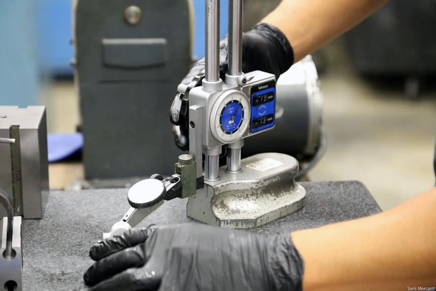
Tips for Controlling The Precision of Part In CNC Machining

Tips for Controlling The Precision of Part In CNC Machining

CNC machining precision is the degree to which the three geometric parameters of the actual size, shape and position of the surface for the processed part conform to the ideal geometric parameters required by the drawing. Ideal geometric parameters are the average size for dimensions; for surface geometry, they are absolute circles, cylinders, planes, cones, and straight lines and so on; for the mutual positions of surfaces, they are absolutely parallel, Vertical, coaxial, symmetrical, etc. The deviation of the actual geometric parameters of the part from the ideal geometric parameters is called the machining tolerance. The deviation of the actual geometric parameters of the part from the ideal geometric parameters is called the machining tolerance.

1.The Concept of CNC Machining Precision

Machining precision is mainly used for the degree of product production,CNC Machining precision and machining error are terms used to evaluate the geometric parameters of the machined surface. Machining precision is measured by tolerance grade, when the tolerance grade value is smaller and stands for the precision is higher; the machining error is expressed by a numerical, when the numerical is larger which stand for the machining error is greater. Highly machining precision means machining error is tiny, and vice versa. According to the applicable field and effective scope of the standard, it is generally divided into: international standards, such as ISO, IEC are standards established by the International Standardization Organization and International Electrotechnical Commission; regional standards, such as EN, ANSI, DIN, are respectively the European Union, the United States, Standards developed by Germany.

cnc-machined-parts
Tolerance Level

There are total of 20 tolerance levels from IT01, IT0, IT1, IT2, IT3 to IT18. IT01 indicates the highest machining precision of the part, and IT18 indicates the lowest machining precsion of the part. Generally, IT7 and IT8 are middle-level machining precision.

Guaranteed Machining Accuracy

The actual parameters obtained by any machining method will not be absolutely accurate. From the perspective of the function of the part, as long as the machining error is within the tolerance range required by the part drawing, it is considered that the machining accuracy is guaranteed.

Quality of CNC Machines

The quality of the machine depends on the processing quality of the parts and the assembly quality of the machine. The processing quality of the parts includes two major parts, the accuracy of the parts and the surface roughness.

Machining Precision

Machining precision is the degree to which the three geometric parameters of the actual size, shape and position of the surface for the processed part conform to the ideal geometric parameters required by the drawing. The difference between them is called machining error. The size of the machining error reflects the level of machining precision. The machining error is greater stand for the machining precision is lower, and the machining error is smaller stand for the machining precision is higher.

2.Related information for CNC machining precision

Dimensional precision

Dimensional precision refers to the degree of conformity between the actual size of the processed part and the center of the tolerance zone of the part size.

Positional precision

Positional precision refers to the actual position precision difference between the relevant surfaces of the parts after processing.

Shape Precision

Shape precision refers to the degree of conformity between the actual geometry of the surface of the processed part and the ideal geometry.

Interrelationship

Generally, when designing machine parts and specifying the machining precision of parts, attention should be paid to control the shape error within the position tolerance, and the position error should be smaller than the dimensional tolerance. For precision parts or important surfaces of parts, the shape precision requirements should be higher than the position precision requirements, and the position precision requirements should be higher than the dimensional precision requirements.

3.Adjustment method

  • (1) Adjust the process system

  • (2) Reduce machine tool errors

  • (3) Reduce the transmission error of the transmission chain

  • (4) Reduce cutters wear

  • (5) Reduce the forced deformation of the process system

  • (6) Reduce thermal distortion of the process system

  • (7) Reduce residual stress

4.Cause of impact

(1) Machining principle error

Machining principle error refers to the error produced by processing with approximate blade profile or approximate transmission relationship. The machining principle errors mostly appear in the machining of threads, gears, and complex 3D surfaces.

During machining, approximate processing is generally used to improve productivity and economy on the premise that the theoretical error can meet the processing precision requirements.

Precision of Part In CNC Machining

(2) Adjustment error

The adjustment error of the machine tool refers to the error caused by inaccurate adjustment.

5 AXIS CNC MACHINING CENTER-2 (1)

(3)Machine tool error

Machine tool error refers to the manufacturing error, installation error and wear of the machine tool. Mainly include the guide error of the machine tool, the rotation error of the spindle of the machine tool, and the transmission error of the machine tool transmission chain. This is caused by the machine error of the manufacturing machine, which is also called the industrial master machine. In other words, any actual size is not absolute, only relative. Just like there is no absolute circle in this world, because there is an infinite value behind π3.1415926.

5 .Measurement methods

The machining precision adopts different measurement methods according to different machining precision content and preicison requirements. Generally speaking, there are the following types of methods:

(1) According to whether direct measures the measured parameter, it can be divided into direct measurement and indirect measurement.

Direct measurement: Directly measure the measured parameters to obtain the measured size. For example, use calipers and height gauges to measure.

Indirect measurement: Measure the geometric parameters related to the measured size, and obtain the measured size through calculation.For example: measuring two sizes can get another size.

Auxiliary fixture for measurement:Make the opposite shape to the part for check the assembly size of the part.

Obviously, direct measurement is more intuitive, and indirect measurement is more cumbersome. Generally, when the measured size or direct measurement fails to meet the precision requirements, then has to use indirect measurement.

Quality-Inspection

(2) According to the reading value of the measuring tools whether directly represents the numeric of the measured size, it can be divided into absolute measurement and relative measurement.

Absolute measurement: The reading value directly indicates the size of the measured size, such as measuring with a vernier caliper, micrometer.

Relative measurement:The reading value only indicates the deviation of the measured size from the standard measurement. For example, to measure the diameter of the shaft with a comparator, first you need to adjust the zero position of the measuring tools with a gauge block, then to process the measurement; the measured value is the difference between the diameter of shaft and the size of the gauge block, which is called relative measurement. Generally speaking, the accuracy of relative measurement is higher, but the measurement is more complex. Need to make auxiliary fixture for measurement.

(3) According to whether the surface to be measured is in contact with the measuring head of the measuring tools, it is divided into contact measurement and non-contact measurement.

Contact measurement: The measuring head is in contact with the touched surface, and there is a mechanical measuring force. For example, measure the parts with micrometer.

Non-contact measurement: The measuring head is not in contact with the surface of the measured parts, and non-contact measurement can avoid the influence of the measuring force on the measurement result. For example, use projective Measurement to do the measurement.

contact measurement

(4)According to the number of measurement parameters, it is divided into single measurement and comprehensive measurement.

Single measurement: Measure each parameter of the tested part separately.

Comprehensive measurement: Measure the comprehensive index reflecting the relevant parameters of the part. For example, when using microscope to measure the thread, the actual pitch diameter, the half-angle error of the tooth profile and the cumulative error of the thread pitch can be measured separately.

Generally comprehensive measurement is more efficient and more reliable to ensure the interchangeability of parts, and usually use for inspection of finished parts. Single measurement can determine the error of each parameter separately, and is generally used for process analysis, process inspection, and measurement of specified parameters.

comprehensive measurement

(5)According to the role of measurement in the machining process, it is divided into active measurement and passive measurement.

Active measurement: The workpiece is measured during the machining process, and the result is directly used to control the processing of the part, thus to prevent the defective parts happened.

Passive measurement:Measurement after workpiece completed machining. Such measurement only able to use for judge the workpiece is qualified or not, and is limited to discovering and rejecting defective parts.

CNC Machining Parts
Aluminum 6061 or 7075
CNC Milling Parts

(6)According to the state of the measured part in the measurement process, can be divided into static measurement and dynamic measurement.

Static measurement:The measurement is relatively static. Such as measure diameter with micrometer.

Dynamic measurement:During measurement, the measured surface relative motion between the measuring head in the simulated working state.  

The dynamic measurement method can reflect the situation when the part is close to usage conditions, which is the development direction of measurement technology.